3.8k
In this article, we connect a KY-024 Linear Magnetic Hall module to a Raspberry Pi Pico, any Rp2040 type board will be suitable. We actually tested this with a Cytron Maker Pi Pico
We will use Micropython for these examples but of course you can use the Arduino IDE as well if you have Raspberry Pi Pico support enabled
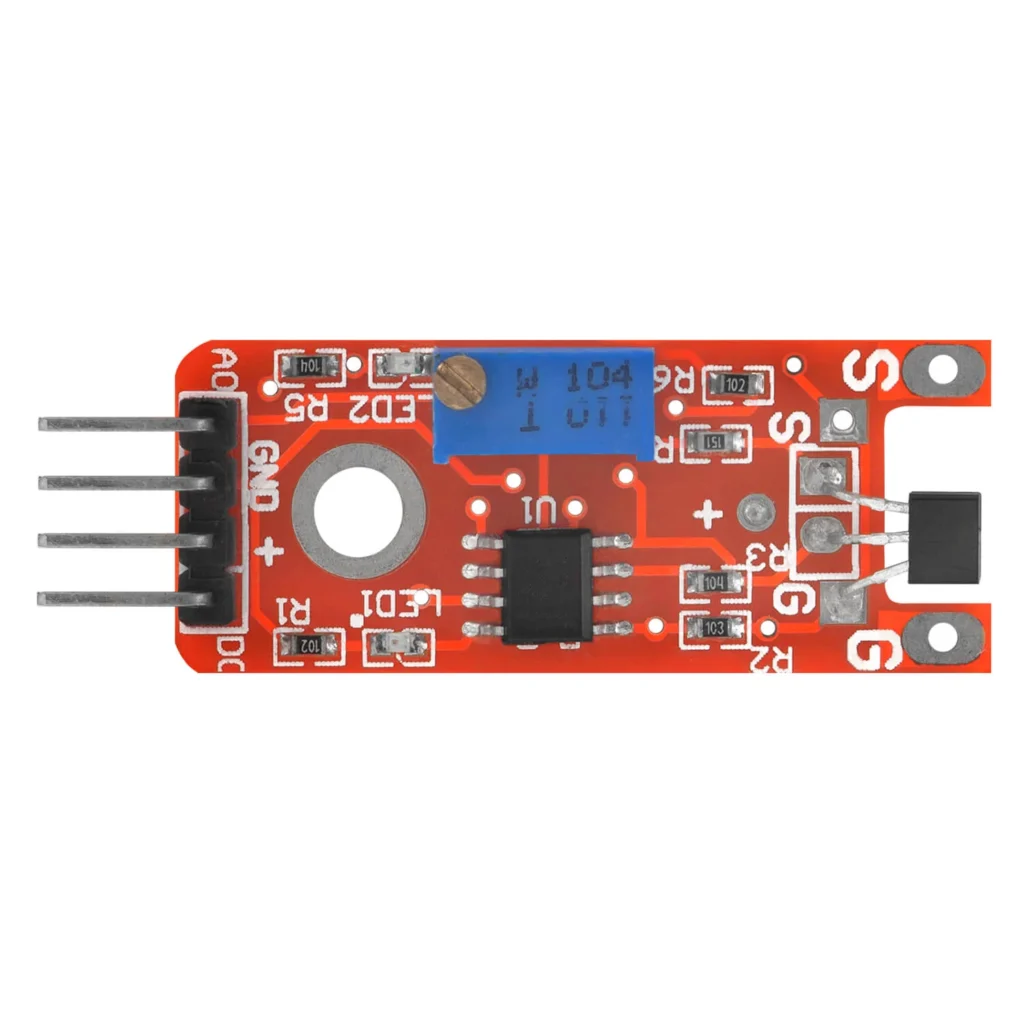
KY-024 Linear Magnetic Hall module Overview
- Function: Detects magnetic fields, providing both analog and digital outputs.
- Applications:
- Proximity sensing
- Speed measurement
- Magnetic field detection
- Robotics and automation
Pinout and Connections
| Label | Description |
|---|---|
| + | Power supply (3.3V – 5V) |
| GND | Ground |
| A0 | Analog output (proportional to field strength) |
| D0 | Digital output (ON/OFF based on threshold) |
How It Works
- Analog Output (A0):
- Provides a continuous voltage that increases or decreases with magnetic field strength.
- Useful for detecting field intensity.
- Digital Output (D0):
- Triggers HIGH or LOW depending on the magnetic field exceeding a threshold.
- Adjustable threshold via onboard potentiometer.
Adjusting Sensitivity
- Potentiometer on the sensor board adjusts the sensitivity for the digital output (D0).
- Clockwise: Increases sensitivity.
- Counterclockwise: Decreases sensitivity.
Technical Specifications
| Feature | Value |
|---|---|
| Operating Voltage | 3.3V to 5V |
| Output Type | Analog (A0), Digital (D0) |
| Detection Range | ~0 to ±150 milliteslas (mT) |
| Adjustable Sensitivity | Yes (via potentiometer) |
| Module Size | 32mm x 14mm |
| Indicator LEDs | Power and Digital output LEDs |
Testing and Calibration**
- Power On: Connect the sensor to the Arduino (or another microcontroller).
- LED Indicators:
- Power LED (ON when powered).
- D0 LED (Lights up when magnetic field exceeds the threshold).
- Adjust Potentiometer: Rotate until the desired sensitivity is achieved.
Practical Applications
- Magnetic Door Sensors
- Speed Sensors (rotating magnets)
- Contactless Position Sensing
- Current Sensing (in circuits with high magnetic interference)
Parts Required
You can connect to the module using dupont style jumper wire.
| Name | Links |
| Raspberry Pi Pico | |
| 37 in one sensor kit | |
| Connecting cables |
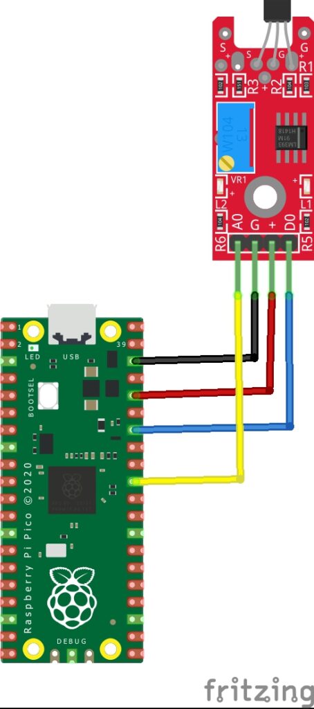
Schematic/Connection
| Pico | Sensor |
|---|---|
| GPIO26 | A0 |
| GND | GND |
| 3 V | +V |
| GPIO28 | D0 |
Code Examples
from machine import Pin, ADC
from time import sleep

# Initialization of pins
adc = ADC(0)
digital = Pin(28,Pin.IN, Pin.PULL_UP)

print("KY-024 Sensor")

# Endless loop for reading out the ADC
while True:
    raw_value = adc.read_u16()
    # Conversion from analog value to voltage
    Volt = round(raw_value* 3.3 / 65536, 2)
    digital_value = digital.value()

    # Serial output of the analog value and the calculated voltage
    print("Analog voltage value: " + str(Volt) + " V\t Threshold value: ", end="")

    # Query whether the digital value has changed with serial output
    if digital_value == 1:
        print("reached")
    else:
        print("not reached")

    print("----------------------------------------")
    sleep(2)
REPL Output
Disclaimer
This website may contain affiliate links, which means we may receive a commission if you click on a link and make a purchase. This comes at no additional cost to you.